![]()


Lightning Warning System
System Overview
This project extends the existing lightning warning system from local only annunciation of lightning warnings and alerts, to automatic site wide warnings and alerts. A new configuration file was placed on the PC and an interface termination box was added to the existing lightning warning PC digital I/O board via a ribbon cable (refer to drawing E-TR-01) in order to access the warning (amber) and alert (red) conditions. The warning and alert signals are then connected to a radio frequency transmitter. The transmitter broadcasts the warning or alert signal site wide to automatically activate corresponding beacons. Currently, there are 23 receivers activating 26 sets of beacons located on the landside and airside terminal rooftops.
System Hardware
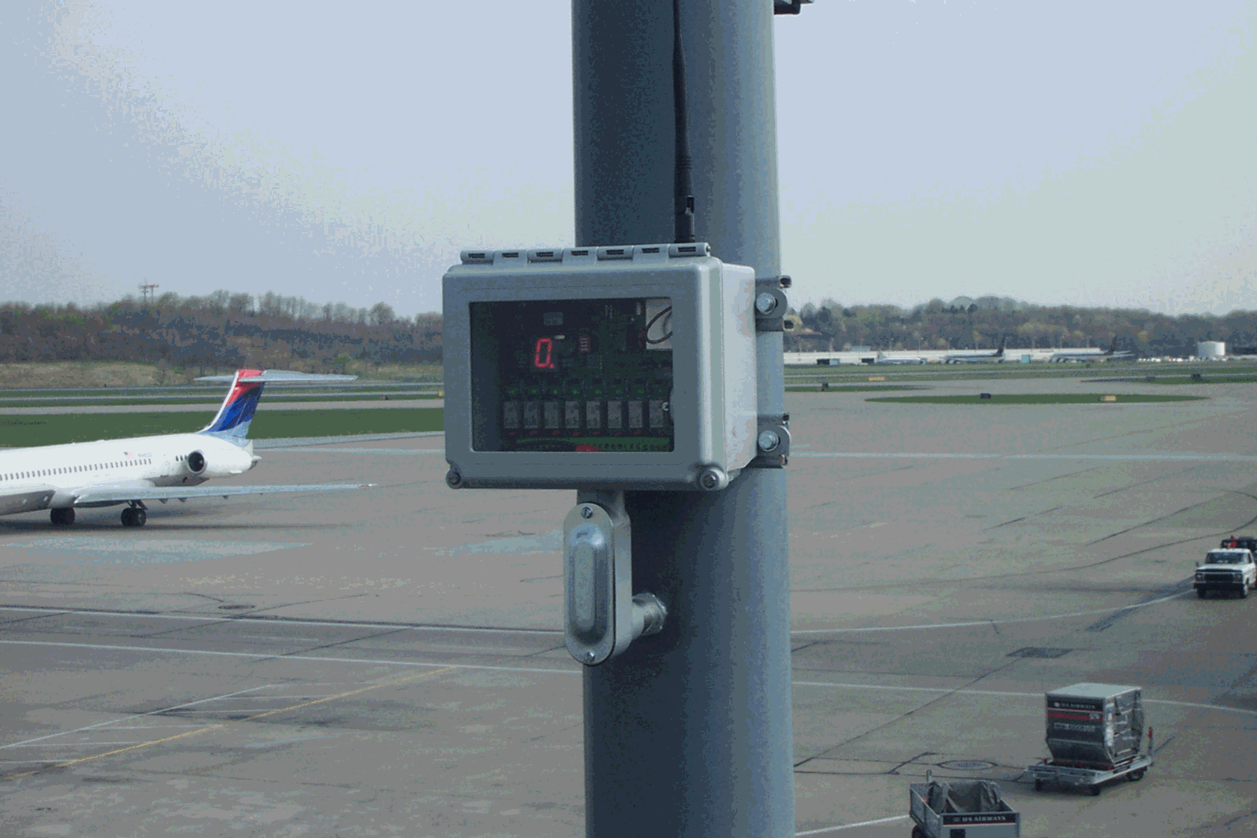
1. Interface Box (STA-U). Location: Airside Emergency Operations Center console.

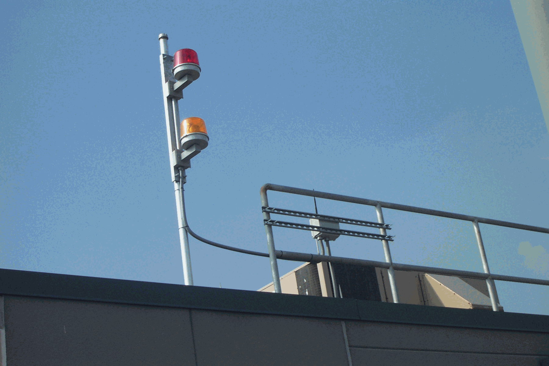
2. Transmitter. Location: One floor above Airside Emergency Operations Center in riser closet. Antenna located on the roof above.
Transmitter Antenna Location
![]()

3. Receivers. Locations: 20 on the airside terminal rooftops, 3 on the landside terminal commuter area rooftops.
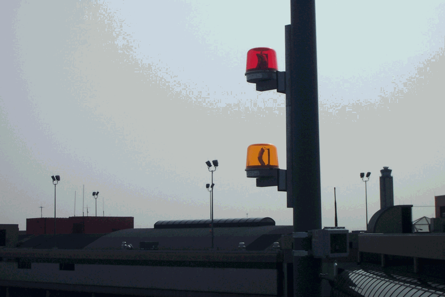
4. Beacon Assemblies. Locations: 20 on the airside terminal rooftops, 6 on the landside terminal commuter area rooftops.
Landside Airside
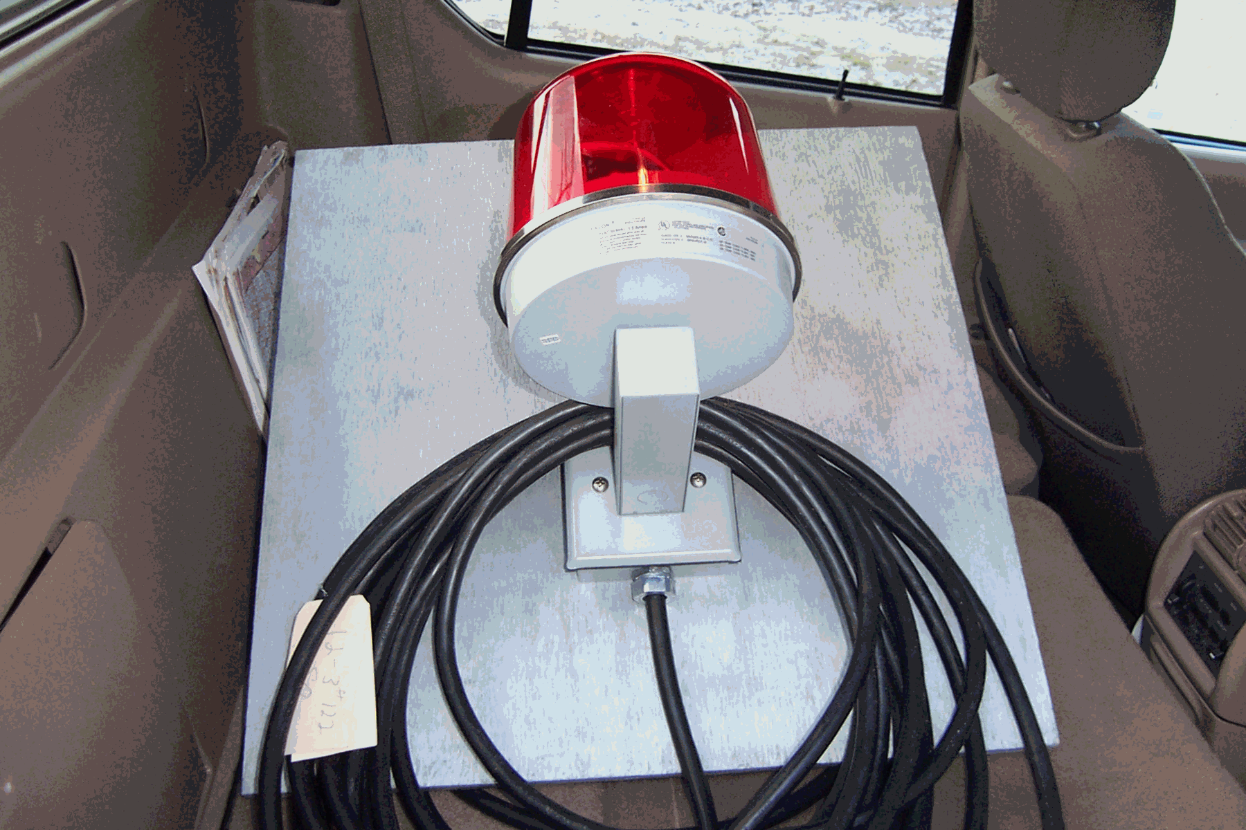
5. Portable Receiver and Beacon assemblies. For use at temporary job sites.
Operation
1. Lightning Warning system detects and annunciates the current lighting condition and activates the interface relays as follows:
Green (all clear) – no relay, no beacon activation. A number 0 is displayed at all receivers. No receiver relays are activated.
Amber (warning) – relay OP1 activated, amber LED lights on transmitter and activates all remote amber beacons. A number 1 is displayed at all receivers. Receiver relays 1 and 2 are activated.
Amber/Red (warning) – relay OP1 remains/activates, amber LED lights on transmitter and activates all remote amber beacons. A number 1 is displayed at all receivers. Receiver relays 1 and 2 are activated.
Red (Alert) – Relay OP1 clears and relay OP2 activates, amber LED and beacons clear, red LED lights on transmitter and activates all remote red beacons. Receiver relays 3 and 4 are activated. Note: the Red (Alert) condition will remain activated for a minimum of 10 minutes even if alert condition clears. A number 2 is displayed at all receivers.
2. A TEST push button is located on the front of the transmitter box (see above figure). This allows for testing of the system without activating any beacons. When pressed a test signal is transmitted to all receivers and a number 3 is displayed at all receivers. Receiver relay 5 is activated. Note: if an actual warning or alert condition occurs while in test the warning or alert signal will override the test signal.
3. A portable receiver and beacon assembly was provided so that the lightning warning system can be utilized at temporary work sites. Watertight plugs and receptacles are provided for power, red beacon and yellow beacon signals. Each of these plugs/receptacles is physically different so that connections cannot be made wrongly. Operation of the portable unit is the same as described above.
***For any additional information please contact PI Engineering
![]()